
English 


Views: 0 Author: Site Editor Publish Time: 2026-07-01 Origin: Site


Transitioning from semi-automatic manual processes to a fully integrated packaging workflow represents a massive operational shift. Facility managers and operations directors must constantly balance aggressive throughput demands against tight facility footprint constraints and essential changeover flexibility. Scaling up production introduces serious mechanical challenges. Improper equipment matching often causes workflow bottlenecks, extensive product waste, and severe downtime. You need systems perfectly synchronized to handle daily production rigors without constant operator intervention.
Our goal is to move beyond basic machine definitions. We will provide an engineer-level breakdown of line components, configuration options, and the critical evaluation criteria required to avoid integration pitfalls. You will learn how to match pump technologies to fluid viscosities, select the right structural architecture, and navigate hidden rollout risks. By understanding these technical nuances, you can implement robust solutions and keep your operations running smoothly at maximum efficiency.
A complete system integrates primary dosing, closure application, and branding into a synchronized workflow, but its true value lies in PLC communication between these stations.
Configurations generally split between linear inline architectures (high flexibility) and rotary/monobloc systems (high speed, compact footprint).
Evaluating an automatic bottling line requires scrutinizing Clean-in-Place (CIP) capabilities, tooling changeover times, and material compatibility over stated maximum outputs.
Successful implementation relies heavily on Factory Acceptance Testing (FAT) using exact production containers and bulk fluids.
An advanced packaging workflow functions as a cohesive ecosystem rather than a collection of isolated machines. The process begins the moment empty containers enter the system. Containers move seamlessly from accumulation tables and unscramblers into the primary packaging phases. Synchronized conveyor control acts as the central nervous system. Variable Frequency Drives (VFDs) and photo-eye sensors communicate constantly, adjusting conveyor speeds to prevent container tipping or line starvation. This synchronized movement ensures each bottle arrives at the dosing, capping, and labeling stations at precisely the right moment.
Matching your fluid viscosity to the correct pump technology dictates your overall filling accuracy. Thick gels and heavy creams require positive displacement solutions like piston pumps. These pumps physically push highly viscous materials through the nozzle using a cylinder mechanism. Conversely, thin or foamy liquids perform best using gravity or overflow fillers. Overflow systems fill containers to a specific cosmetic level regardless of minor interior volume variations. For high-purity pharmaceutical applications, peristaltic pumps isolate the fluid inside flexible tubing, completely preventing cross-contamination.
Throughput context matters significantly when scaling operations. For mid-range production facilities, a 6-head liquid filling line serves as an excellent baseline example. This configuration allows multiple bottles to fill simultaneously. Operators can easily cap off individual nozzles or expand the manifold based on specific batch sizes. Such modularity provides excellent flexibility when transitioning between small custom runs and large-scale commercial orders.
Applying closures correctly prevents leaks, preserves product integrity, and ensures consumer safety. Modern closure mechanisms typically fall into two primary categories. Spindle cappers utilize sets of spinning discs to tighten screw caps as bottles travel continuously down the conveyor. They excel in high-speed, continuous-motion environments. Chuck cappers operate differently. They descend onto the bottle, gripping the cap firmly, and apply highly precise torque control. Chuck systems work best for unique cap shapes or products requiring strict torque validation.
You cannot discuss capping without addressing cap delivery. A high-speed capper fails instantly if it lacks a consistent supply of closures. Vibratory or centrifugal cap sorters orient bulk caps into the correct position. Elevators then transport these sorted caps up to the delivery chute. Proper sorting prevents inverted caps from jamming the application wheels and causing severe line starvation.
Product branding and regulatory traceability happen at the labeling station. Application types vary widely depending on container geometry. Front and back labelers apply dual panels to flat or oval bottles. Wrap-around systems spin cylindrical containers to apply a continuous label. Top and bottom labelers target the caps and bases of jars or flat-packed items.
Modern integration treats a bottle capping and labeling machine as an intelligent data hub. These machines do more than dispense mechanical stickers. They incorporate Thermal Transfer Overprinters (TTO) or continuous inkjet coders directly into the applicator head. This integration ensures real-time lot codes, expiration dates, and 2D barcodes print clearly on every label, fulfilling strict industry traceability requirements.
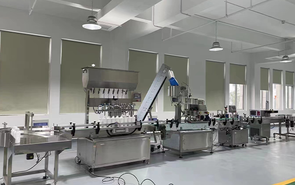
Selecting the right physical layout determines how efficiently your facility operates. Buyers must carefully map their SKU diversity against their available square footage before committing to a structural category.
Inline architectures arrange each packaging station sequentially along a straight conveyor belt. They represent the most common layout in diverse manufacturing environments.
Best for: Operations handling a high product mix, multiple bottle shapes, and highly scalable budgets. You can easily roll a new labeling module up to the existing conveyor line.
Trade-offs: The straight-line design requires a substantially larger facility footprint. Longer conveyor transitions also increase the time it takes a single bottle to travel from start to finish.
Monobloc systems condense multiple packaging functions onto a single rotary starwheel base. The machine grabs the container once and indexes it circularly through filling, plugging, and capping stations.
Best for: Single-product high-speed runs and environments facing severely limited floor space. They dominate the pharmaceutical and high-end cosmetics sectors due to their strict cleanroom compatibility and hygienic enclosures.
Trade-offs: They suffer from highly complex changeovers. Because all actions happen on one integrated chassis, a mechanical failure at one single station instantly halts the entire machine.
To simplify the architectural choice, we structured the primary differences into a comparative matrix.
| Evaluation Criteria | Inline (Linear) Systems | Monobloc (Rotary) Systems |
|---|---|---|
| Footprint Requirements | Large (requires linear length) | Highly compact (circular indexing) |
| Changeover Speed | Fast (easy access to modules) | Slow (complex starwheel replacements) |
| SKU Flexibility | Excellent (handles diverse shapes) | Limited (best for uniform containers) |
| Cleanroom Suitability | Moderate (harder to fully enclose) | Superior (easily fitted with HEPA hoods) |
Looking past the glossy brochures requires a strict focus on mechanical outcomes. Every feature must translate directly into reliable daily production.
Your bulk fluid composition dictates the physical build of the equipment. We must frame this using high-demand scenarios. For example, a heavy-duty detergent bottle filling line handles harsh, abrasive chemicals. Standard stainless steel degrades quickly under such conditions. These specific machines require anti-corrosive contact parts crafted from Titanium, Hastelloy, or high-grade PVC. Furthermore, detergent produces massive amounts of foam. The system must feature specialized diving nozzles that descend to the bottom of the bottle, rising slowly as the liquid fills to prevent severe foaming and splashing.
Marketing materials frequently promise "tool-less changeovers." You must aggressively challenge these claims. Apply Single-Minute Exchange of Die (SMED) principles to evaluate the actual process. Instruct your engineers to scrutinize the physical change parts. Evaluate the star wheels, guide rails, chucks, and sensor mounts. Ask vendors for guaranteed, timed changeover protocols. If operators must unbolt multiple housing units just to adjust a conveyor rail, your facility will bleed profitable production hours every week.
Hygiene dictates product safety. Manual tear-downs pose massive contamination risks. You must prioritize integrated Clean-In-Place (CIP) or Sterilize-In-Place (SIP) systems. CIP allows the machine to flush caustic detergents and sanitizers through the fluid pathways automatically. Address compliance standard lenses relevant to your specific industry sector. Check for cGMP adherence in pharmaceuticals, FDA-approved food-grade welding, and fundamental CE or UL electrical safety certifications.
Hardware runs the product, but software runs the hardware. Highlight the massive risk of proprietary PLC (Programmable Logic Controller) lock-ins. If a vendor uses heavily encrypted, custom-built circuit boards, you become completely dependent on their technicians. We strongly recommend specifying universally recognized platforms like Allen-Bradley or Siemens when ordering an automatic bottling line. Open-architecture controls ensure your localized, in-house maintenance teams can diagnose faults and replace components without begging the Original Equipment Manufacturer (OEM) for permission.
Even the most expensive equipment stumbles if you ignore the environmental realities of the manufacturing floor. Hidden rollout costs destroy project budgets.
Buyers often assume their bottles possess perfect dimensions. Address the reality that raw packaging materials vary wildly. Glass molds leave raised seams. Cheap PET bottles experience wall thickness variations or slight thread pitch anomalies. These dimensional deviations cause immense headaches. A micro-variation in thread pitch leads directly to cross-threading at the capper. A sunken bottle panel results in misaligned labels and wrinkling. The machine's sensor arrays and guide systems must actively accommodate these structural micro-variations.
Production systems follow the absolute "weakest link" principle. A brilliant 100-bottle-per-minute filler proves entirely useless if the downstream cap sorter jams at 60 BPM. Engineers must intentionally design buffering zones into any sophisticated liquid packaging line. Bidirectional accumulation tables absorb the shock of minor downstream faults. If the labeler pauses to load a new roll, the accumulation table temporarily stores the filled bottles. This buffer prevents the filling pump from shutting down, maintaining High Overall Equipment Effectiveness (OEE).
Advanced automated lines radically shift the labor burden. You move away from manual laborers toward skilled electromechanical technicians. Facilities routinely underestimate this transition. Highly complex machinery requires intelligent human oversight. Robust Human-Machine Interface (HMI) troubleshooting screens are mandatory. The HMI should visually pinpoint exact sensor failures rather than displaying cryptic error codes. Comprehensive operational training ensures your staff can actually run the multi-million-dollar asset you just purchased.
Committing capital to industrial machinery requires strict validation. Protect your investment by executing rigorous pre-shipment protocols.
Never accept shipment of a liquid filling capping labeling line without executing a rigorous Factory Acceptance Test. Travel to the manufacturer's facility. Demand they run the equipment at full production speed using your actual product fluid, actual closure caps, and actual label rolls. Simulating production with plain water hides foaming issues, viscosity bottlenecks, and pump cavitation. The FAT provides your final leverage to force mechanical corrections before the equipment arrives at your dock.
Frame the vendor relationship as a 10 to 15-year operational marriage. The initial purchase price matters far less than long-term reliability. Assess their spare parts inventory. Ask about their remote PLC troubleshooting capabilities via secure VPN connections. Verify domestic technician deployment times. If a vendor takes three weeks to fly a mechanic across the world to fix a jammed capper, your production schedule will collapse.
Before requesting vendor quotes, compile a comprehensive User Requirement Specification (URS) document. The URS forces internal alignment on key technical parameters.
Define exact product viscosities across different temperatures.
Establish the absolute maximum and minimum bottle dimensions.
Set a realistic target CPM (Containers Per Minute).
Prepare detailed facility CAD layouts showing power drops and drainage points.
Presenting vendors with a completed URS immediately signals your engineering competence and filters out unqualified suppliers.
An integrated packaging ecosystem operates far beyond a simple series of bolted-together machines. Achieving peak operational performance depends entirely on cross-station synchronization, realistic throughput expectations, and robust mechanical design. When you prioritize intelligent PLC communication, rigorous material compatibility, and comprehensive Factory Acceptance Testing, you eliminate integration bottlenecks before they impact your facility.
Take proactive steps today to modernize your production capabilities. Download a standard URS template to begin outlining your requirements. Contact a specialized application engineer for a detailed footprint evaluation, or send your specific container and fluid samples to an equipment manufacturer for a free technical assessment.
A: Linear systems typically require 15 to 25 feet in length to accommodate the primary stations, not including additional space for accumulation tables or pack-out zones. Monobloc architectures condense these multiple functions onto a circular base, often reducing the footprint to a compact 6x6 foot area, excluding the infeed and outfeed conveyors.
A: Yes, but it requires highly specific engineering. Advanced servo-driven piston or gear pumps can manage a wide viscosity spectrum. However, extreme variations usually require interchangeable pump carts or necessitate significantly reduced production speeds when processing thicker paste products.
A: Lead times generally range from 12 to 24 weeks. This timeframe heavily depends on the level of mechanical customization, the complexity of your Factory Acceptance Testing requirements, and ongoing supply chain constraints affecting specific PLC and sensor components.
A: Foaming products require specialized setups. You must use bottom-up filling methods where diving nozzles descend into the bottle and rise simultaneously with the fluid level. Incorporating overflow or gravity mechanisms also helps manage foam expansion without forcing operators to slow down baseline production speeds.

